
Metal Bending Terminology
Want to understand more about how sheet metal fabrication works? Read on! Not everything in this section is necessary for you to design a good sheet metal part, but the information about flange length, bend radius, and k-factor is particularly useful.
Flange Length
In a bent sheet metal part, the flange length is the distance from where the punch bends the metal, to the edge of the part, or to the next major feature like another bend.
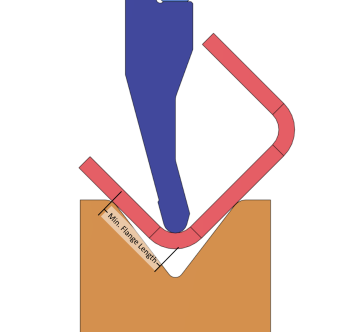
In an air bending operation in particular, the amount of flange area left open matters a great deal. If there is not enough flange on both sides of the bend, the die will lose contact with your part and it won't form properly. Our system will automatically detect if there is insufficient flange support to form your part with our punches and dies.
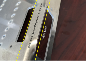
It is also important to keep the flange region free of cutouts. If the die is not in contact on both sides of the punch at all time, some regions of metal may not bend properly:
Bend Radius
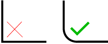
In a bent sheet-metal part, the Bend Radius is the radius of the bent metal where the punch meets the part. In an air-bending process, exact 90 degree angles are not possible to manufacture. There will always be a radius on the bend, as shown below:
K-Factor
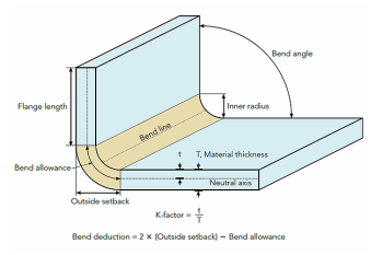
K-factor is the ratio between the "neutral axis" of a bent part and the thickness of the material. The "neutral axis" is where the material doesn't elongate or compress during the bend.
For example, when you bend a metal part, the outside of the bend has to elongate, and the inside of the bend compresses. Somewhere in the middle, the metal does neither. This is what the k-factor defines.
Usually, you don't use k-factor directly. If you use CAD software to model your bent part and create your flat pattern for manufacturing, you'll usually tell it the k-factor so that it knows how to unfold your part to create the flat pattern. Combined with the material bend radius, the k-factor allows the computer to figure out exactly how your part will stretch during bending. It will compensate for that when unfolding your part, so that the finished part is as close as possible to your design.
You can calculate deductions and offsets yourself, if you'd rather not use CAD. But if the finished size of your part is important, we highly recommend that you use CAD software so that you are certain that your flat pattern and bend locations produce the part that you need.
Bend Deductions
In a bent sheet-metal part, the Bend Deduction is the amount the material will stretch when bending your part. Because the material will stretch during the bend, the total length of the part - including the radiused area where the bend takes place - will be larger than the original flat pattern defined.
If you are creating your bent part in CAD, you usually do not have to worry about bend deductions: you can tell your software what k-factor and bend radius to use for the material, and it will automatically create the correct flat pattern size and bend locations so that the finished part size after bending matches your design.
If you are creating a flat pattern manually, you will either need to compute bend deductions, or use our app to obtain bend deduction and other information for your bend.
Bend Allowance and Outside Setback
Bend Allowance is the length of the arc formed by the "neutral axis" of a bend. During a bend, the outside of the material stretches, and the inside compresses. Somewhere in the middle, the material does neither: the length of that region is the bend allowance length. See the picture below.
When your bend angle is 90 degrees, Outside Setback is the distance between the start of the bend radius, and the edge of the flange (see the picture below). If the bend angle is not 90 degrees, it is the distance from the start of the bend radius, to the tangent point of the outside radius.
Like Bend Deductions, Bend Allowance and Outside Setback can help you manually modify a flat pattern to obtain the correct finished part size. We again highly recommend that you don't do this manually, and that you use sheet metal-capable CAD software instead. If you already know how to do it manually and want to do so, you can use the parameters automatically computed by our web app to finalize the size of your flat and the placement of the bend lines.